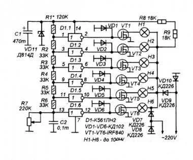
the idea of switching lamps using a regular variable resistor as a control is very good, but the above designs are based on poly comparator chips for LED level indicators. Unfortunately, such chips are not always found in stores. Therefore, using the same principle, I made a switch on the K561LN2 general application logic chip. containing six CMOS inverters.
Portable luminaire dimming control diagram
The schematic diagram is shown in Figure 1. It is based on a six-stage resistance meter R7, in which D1 inverters work as comparators.
Resistors R1 - R7 form a divider, the division ratio of which is regulated by the variable resistor R7. In accordance with the resistance of this resistor, the voltages at the inputs of the logic inverters change. All inverters have almost the same switching thresholds, but their inputs are connected to different parts of the voltage divider.
Therefore, the voltages at their inputs will be different. And depending on the resistance R7, a different number of logic elements will be switched Accordingly, a different number of switches on the VT1-VT2 FETs will be opened, and, therefore, a different number of lamps (or groups of lamps) of the suspended ceiling will be turned on.
Key stages are made on IRF840 field key high-voltage transistors Due to their low resistance in the open state, such switches can, at a voltage of 220V, control a load of up to 100-150 W without any noticeable heating at all. Therefore, they do not need radiators if the total power of lamps connected to one stage does not exceed this value.
The lamps are powered by a pulsating current from a bridge rectifier on VD7-VD10 diodes. The frequency of pulsations at the outlet of the bridge rectifier is twice as high as the frequency of the power supply, so there is less visual fatigue.
The KD226 diodes used allow the total power of all lamps to be no more than 1000W (in reality, without heating, up to 500W). If the power is higher, more powerful diodes are needed. But in the conditions of an apartment, such high power lamps are hardly appropriate.
If the K561LH2 chip is not available, other chips can be used. For example, use two K561LE10 chips or others, so that the total number of elements is at least six. You can also use one K561LE5 or K561LA7 (four elements), reducing the number of keys to four. But replacing the chip will require a rework of the PCB.
Almost all parts (except for the R7 resistor and the lamps themselves) are placed on a printed circuit board with dimensions of 70x60 mm. The seal is one-sided. Figure 2 shows the board diagram with the board facing the reader with the print tracks The diagram shows the location of the radio parts on the board and schematically shows the location of the print tracks and pads.
In fact, the dimensions of the paths and platforms are different The board is made in a rather archaic way - the workpiece is sanded and all the holes are drilled in it, then, the printed tracks are drawn with ordinary bitumen varnish using a sharpened match. After drying, etching in a solution of ferric chloride.
Then rinse the board with gasoline or acetone. The appearance of the tracks will not be very neat, but, in my opinion, the use of a laser iron or photoresist to make a board with loose mounting and only one chip is unreasonably difficult.
Adjustment is reduced to the selection of resistance of resistor R1 so that when the variable resistor knob is turned from one extreme position to the other, all lamps are sequentially lit (or extinguished, depending on the direction of rotation).
ceiling light to switch diagram ceiling light wiring diagram single pole light switch diagram led light switch wiring diagram wiring a light switch suspended ceiling lamp switch diagram pdf suspended ceiling lamp switch diagram printable suspended ceiling lamp switch diagram instructions modern ceiling lamp suspended ceiling lamp switch diagram images ceiling lamp malaysia led ceiling lamp.

